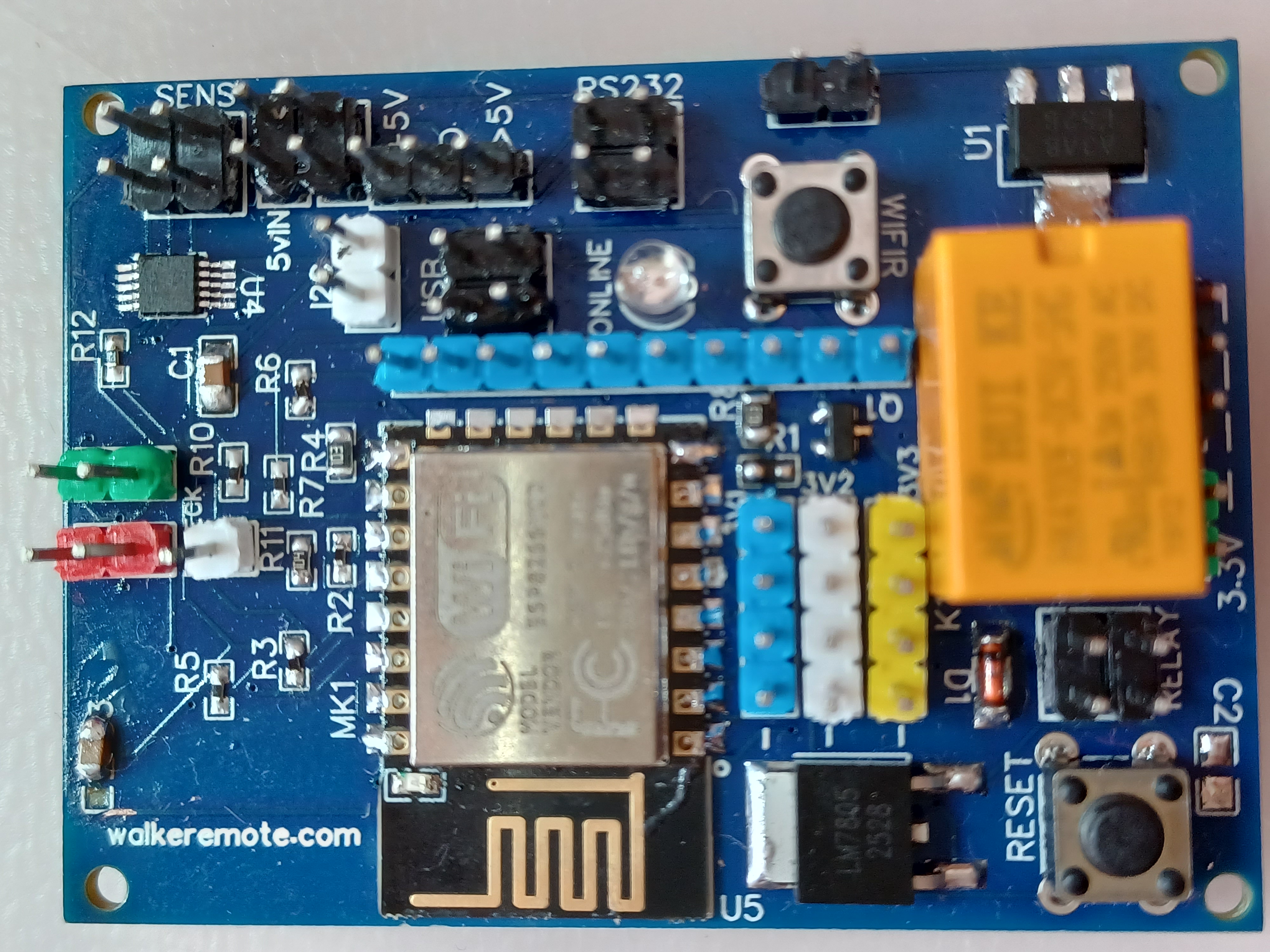
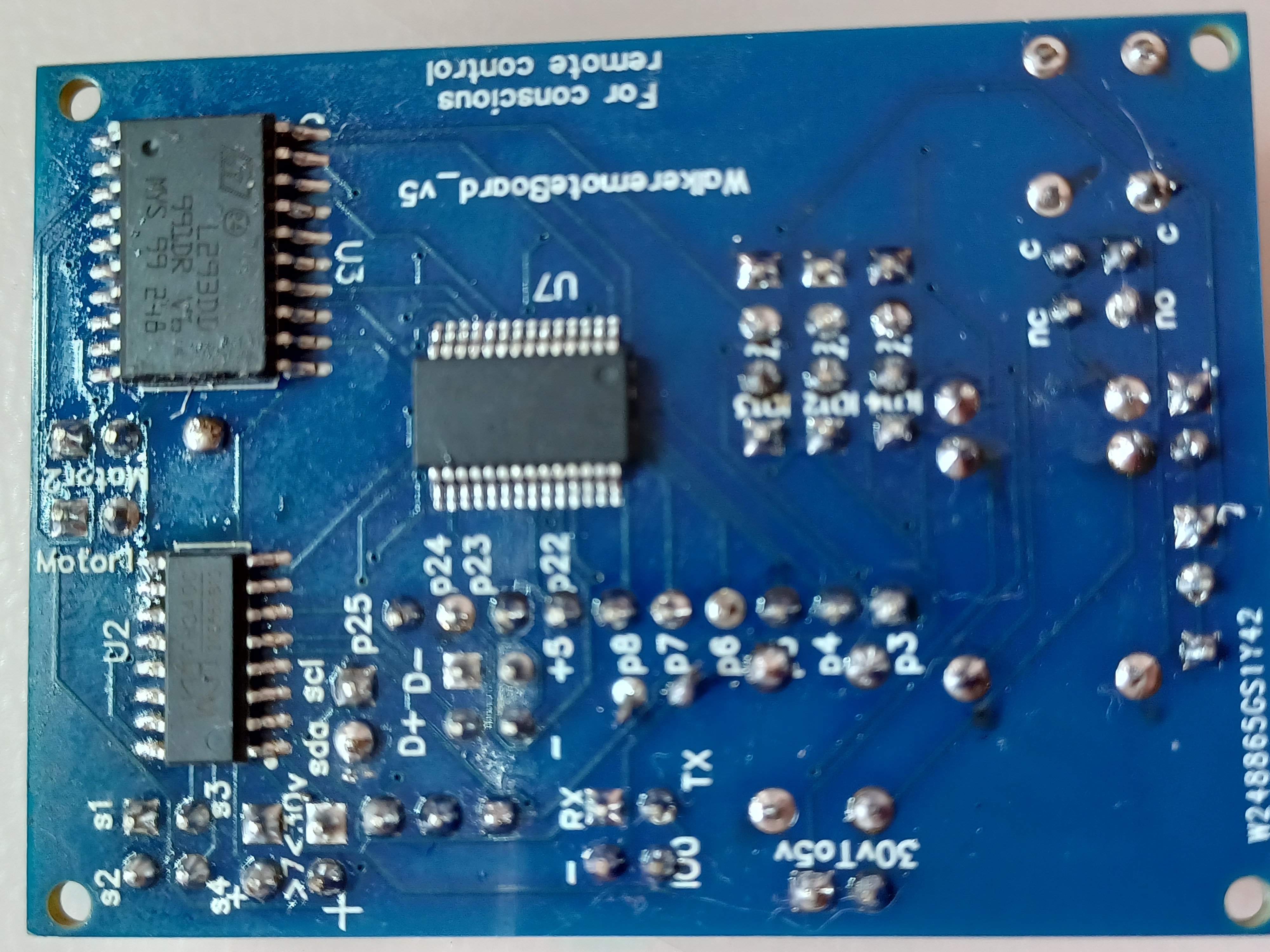
WalkeremoteBoard-rev5: corrections, testing and new experiments
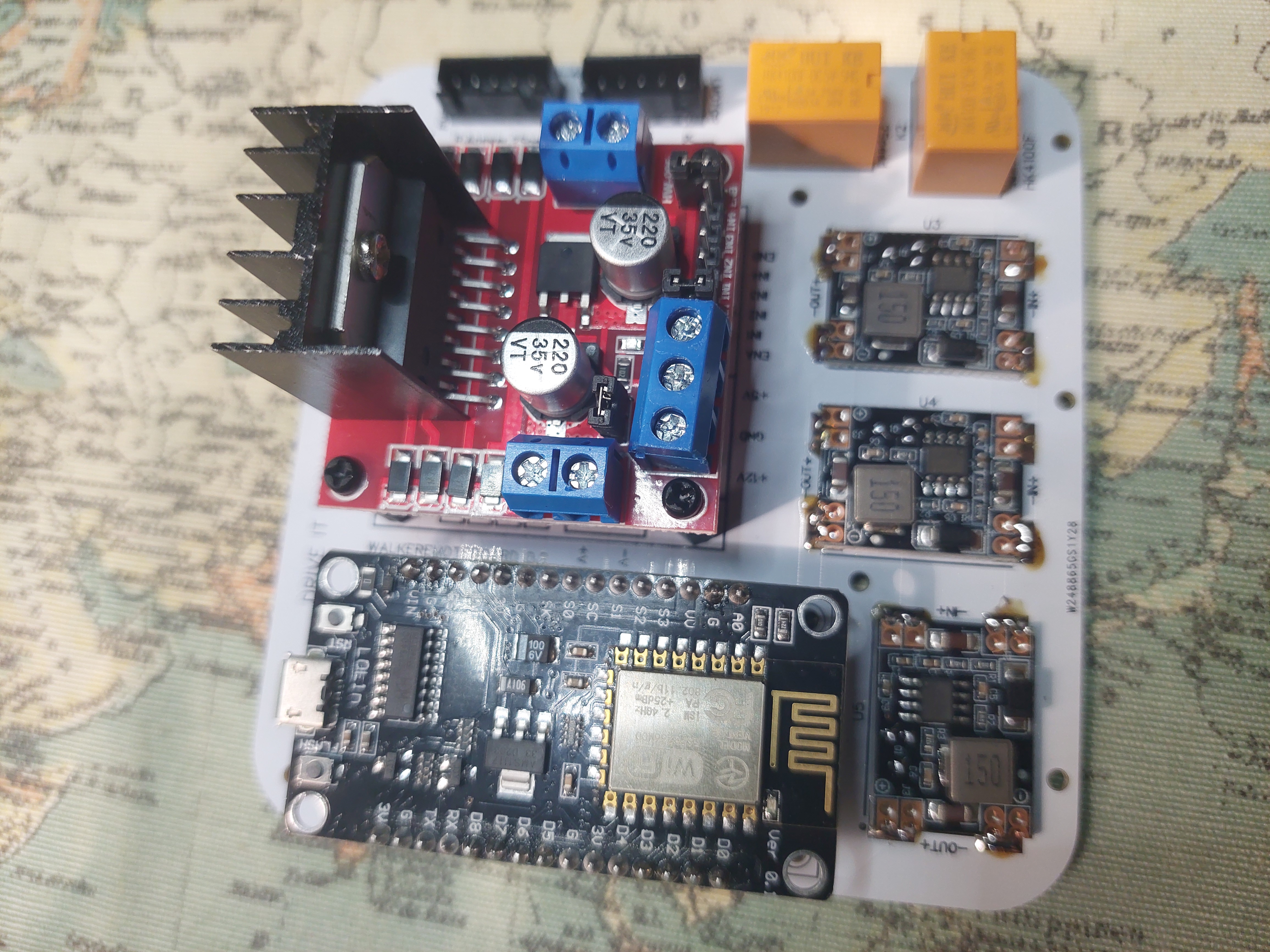
With the WalkerRemote Rev5, I corrected some issues that were present in the previous Rev4.
After having the board manufactured by my trusted factory, I realized that some of the ESP8266
pinouts were not correct. For this reason, I created a new revision, trying to improve the layout
and make the board more stable and functional.
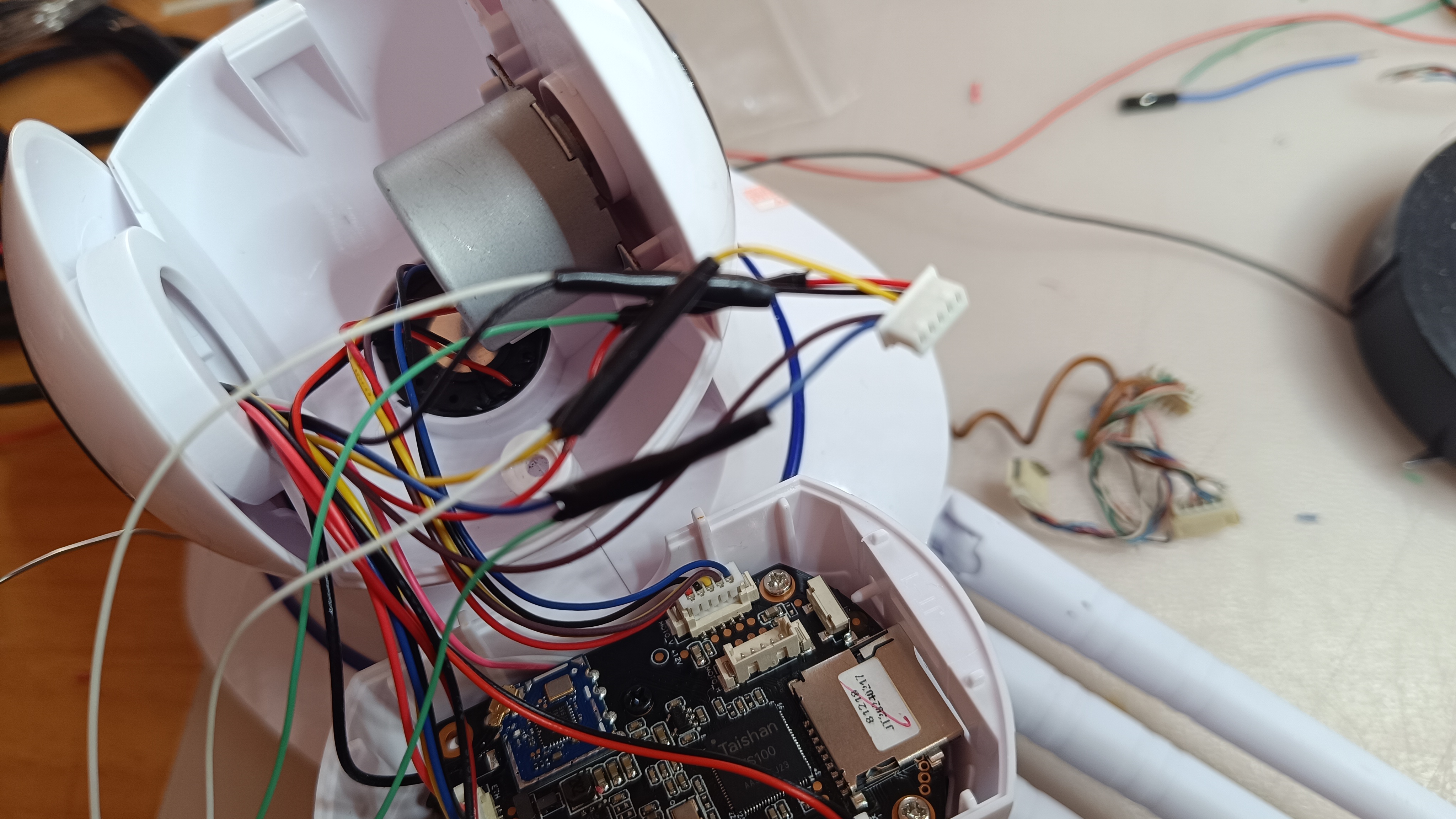
Unfortunately, since I assembled the prototype manually with the few tools I had available —
small hot air station, non-professional flux and recovered components — the final appearance of
the board looks a little rough. However, considering that it is a hand-assembled prototype,
the board works extremely well.
During the assembly, I also encountered some difficulties with the CH340C component,
which is used to interface the USB port with the ESP8266. In particular, I ended up with
a component that apparently did not have the internal 12 MHz crystal, or possibly had some
issue related to resistors with incorrect tolerance. In the end, after desoldering and soldering
another CH340C that I had been using on an old through-hole board, everything started working correctly.
To complete the prototype, I also recovered some resistors by desoldering them from old boards.
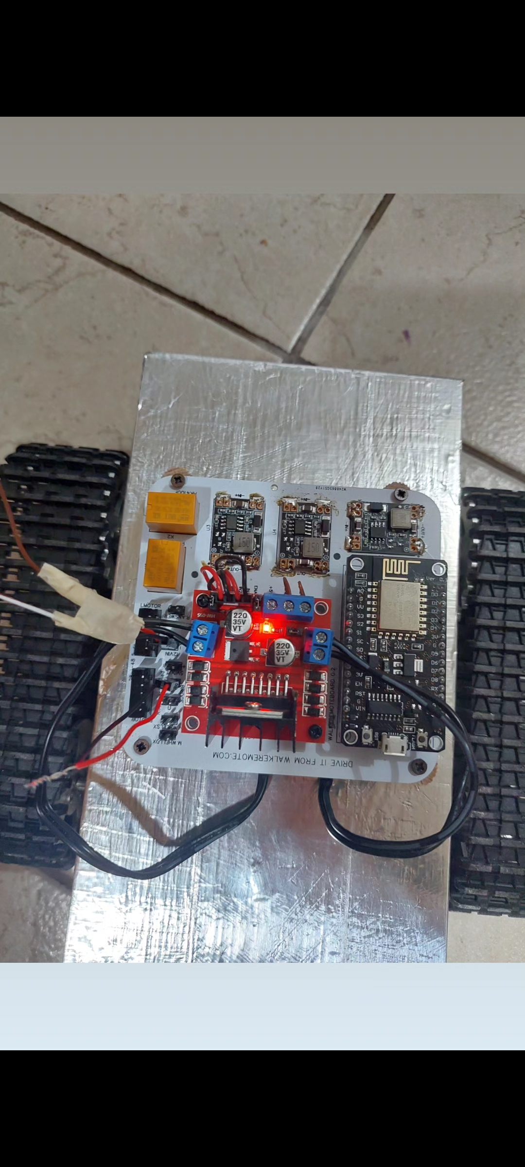
Despite these difficulties, the WalkerRemote Rev5 works perfectly. Of course, the final optimization
will depend heavily on the firmware that will be developed and updated over time.
So far, I have equipped the board with an internal server, from which it is possible
to configure several parameters, including:
Wi-Fi SSID and password for network connection;
the four analog sensor input ports: A0, A1, A2 and A3;
battery voltage reading and calibration values;
enabling or disabling email notifications;
settings related to email addresses, passwords and recipients;
ESC driver values, useful for defining the rotation direction of brushed motors.
The board can therefore be configured directly through a web interface,
without having to manually modify the code every time.
To see the WalkerRemote Rev5 in action, you can watch the videos published on my
YouTube channel at the following link:
Youtube video demonstration
In addition, since I have a strong passion for music and audio experimentation,
I also wanted to test the possibilities offered by the ESP8266’s internal 32-bit processor.
In particular, I started some experiments related to frequency generation, sound effects
and small digital synths.
These experiments will be available in the “Frequencies and Music”
section of the landing page: actionoise.com
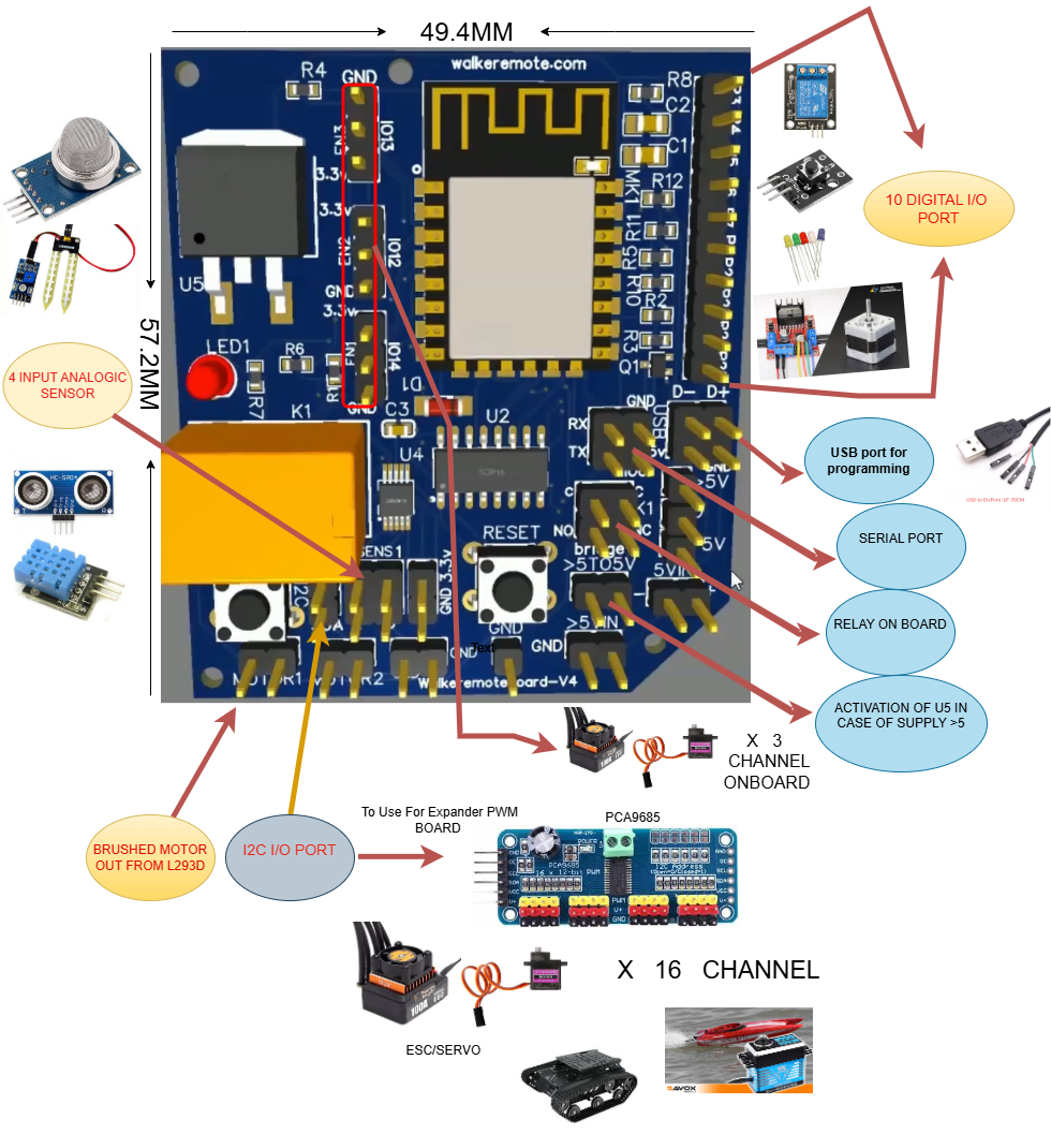
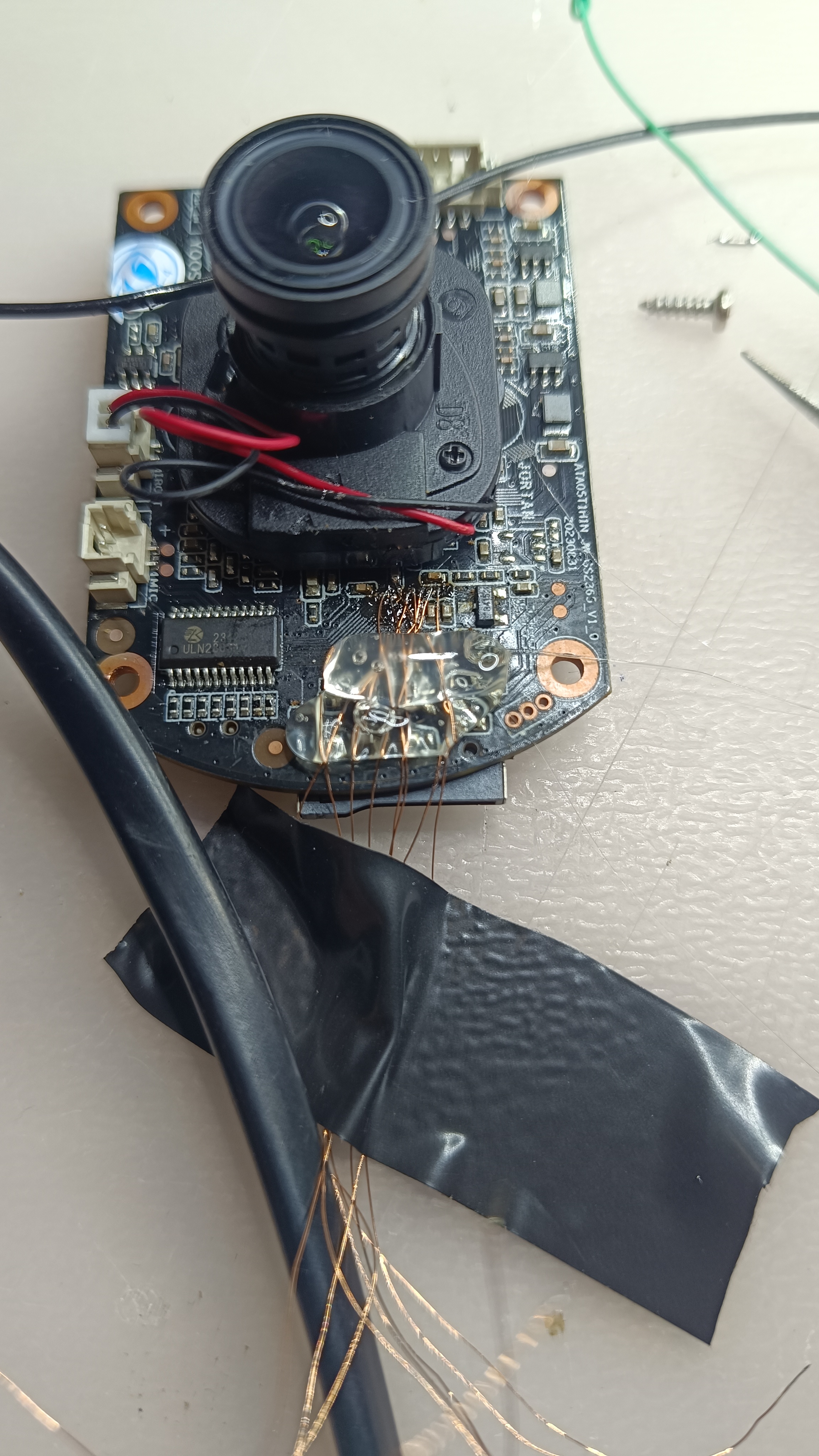
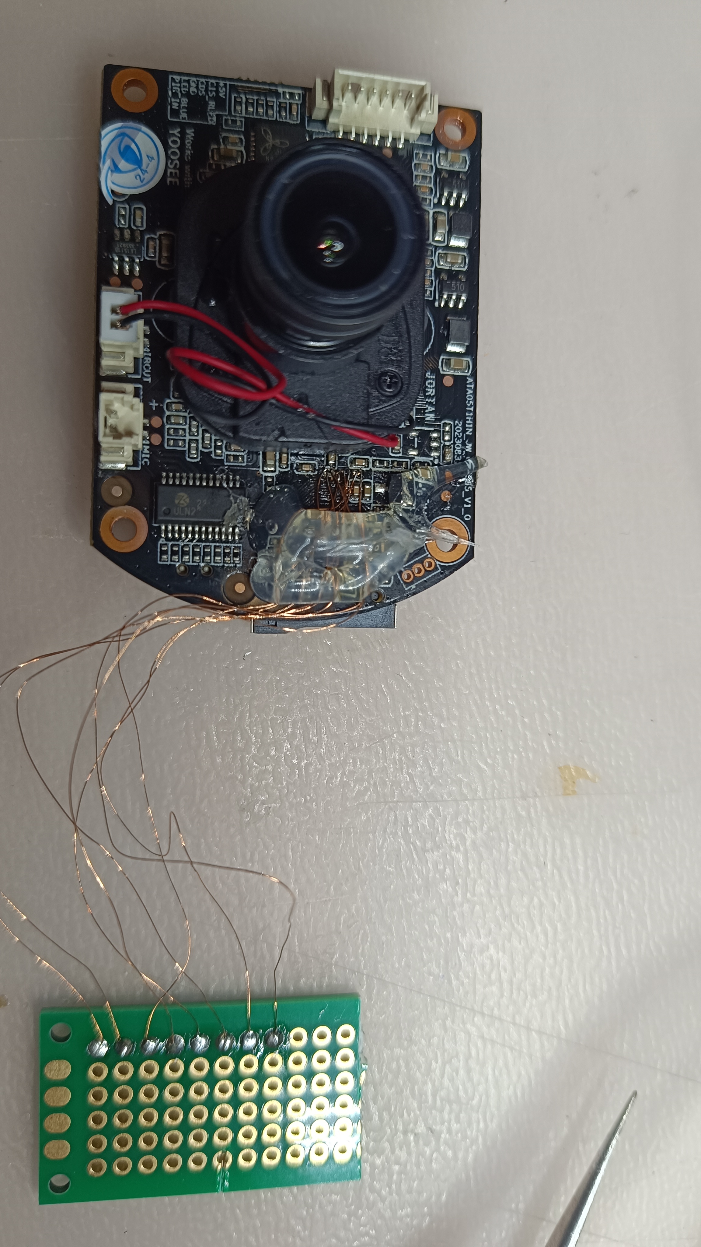
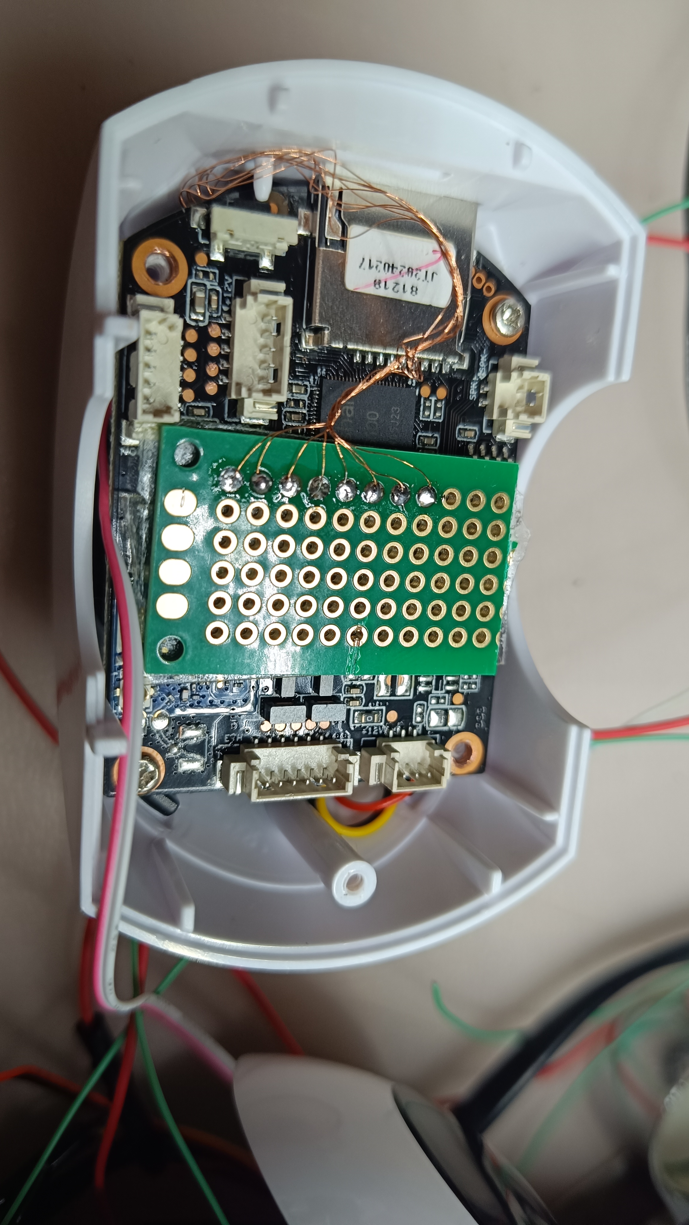
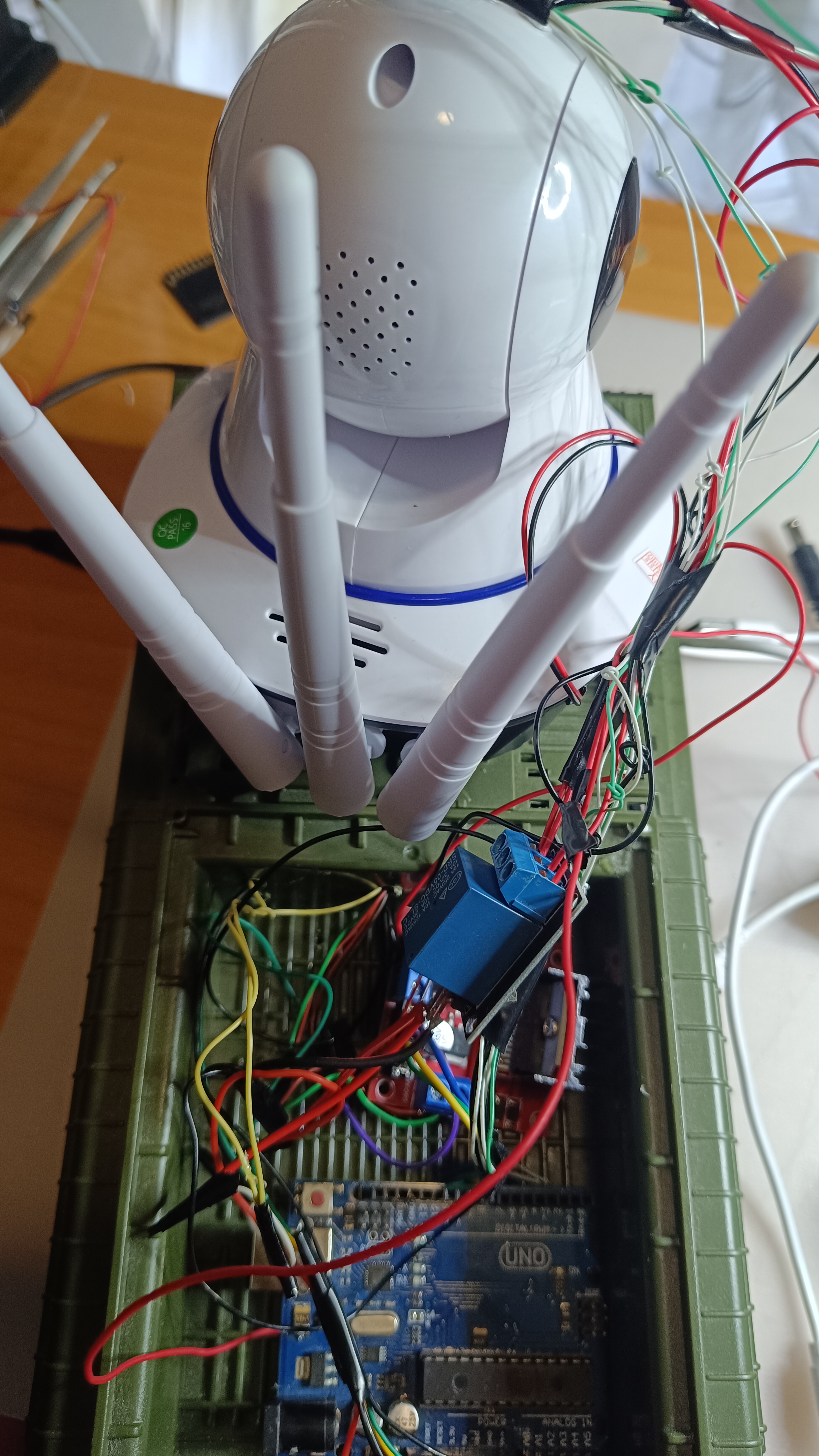
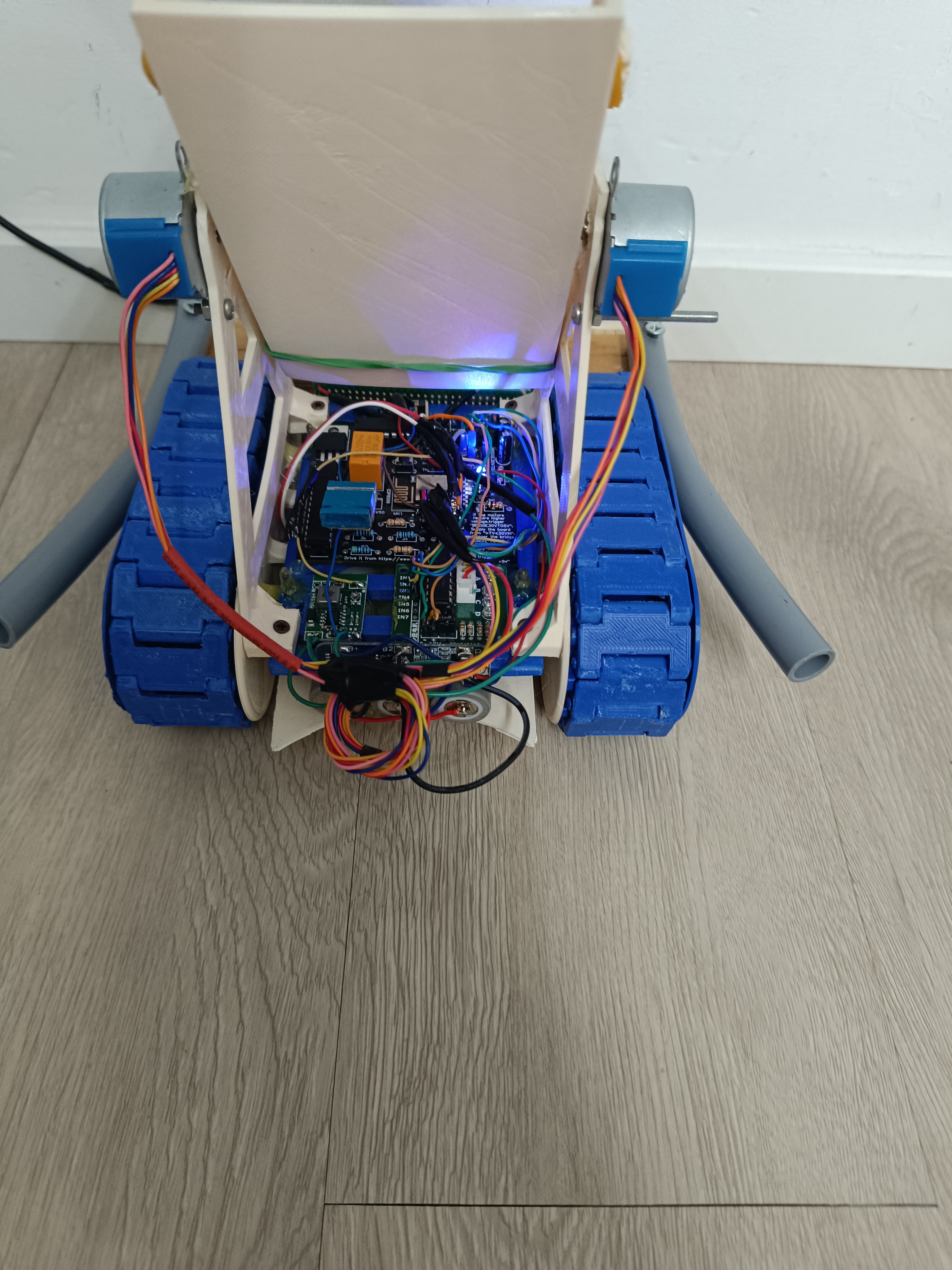
WalkeremoteBoard-rev4 SMD components
As shown in the photos, I developed a new version of the board by reducing its size to about half of the original one
described further down on this page. Despite the more compact design, I added a particularly important component for
analog signal acquisition: the ADS1115, an analog-to-digital converter with an I2C interface. The sensors shown in the
photos are just a few examples among the many analog devices that can be connected.
The ADS1115 was connected to the ESP8266 I2C bus through the SDA and SCL lines, while the ADDR pin of the ADS1115 was
connected to GND in order to set its I2C address to 0x48. This configuration makes it possible to clearly differentiate
it from the MCP23017, which continues to operate normally on the same I2C bus using a different address. In addition,
the SDA and SCL pins have been left available for the connection of further compatible
I2C peripherals with different addresses.
As shown in the images, the board also allows the connection of motor ESCs, as well as additional sensors or microcontrollers,
making it possible to significantly expand its functionality.
On the opposite side of the board there is the BattCheck pin, which, through a resistor divider, is connected to the A0 pin of the
ESP8266. This makes it possible to remotely monitor the battery voltage through a dedicated function already implemented in the
source code.
When used with drone ESCs, the board can be powered directly by using the 5V output that some ESCs provide for powering radio
receivers. If, on the other hand, motors driven by the onboard L293D driver are used, it is possible to enable the 5V
regulator through the bridge shown in the photos and power the motor driver with a higher voltage, up to 30V, through
the dedicated D pin.
Finally, I added three additional I/O pins: IO12, IO13, and IO14, which can be used to enable or disable extra functions,
or simply to control ESCs, servos, or other compatible devices.
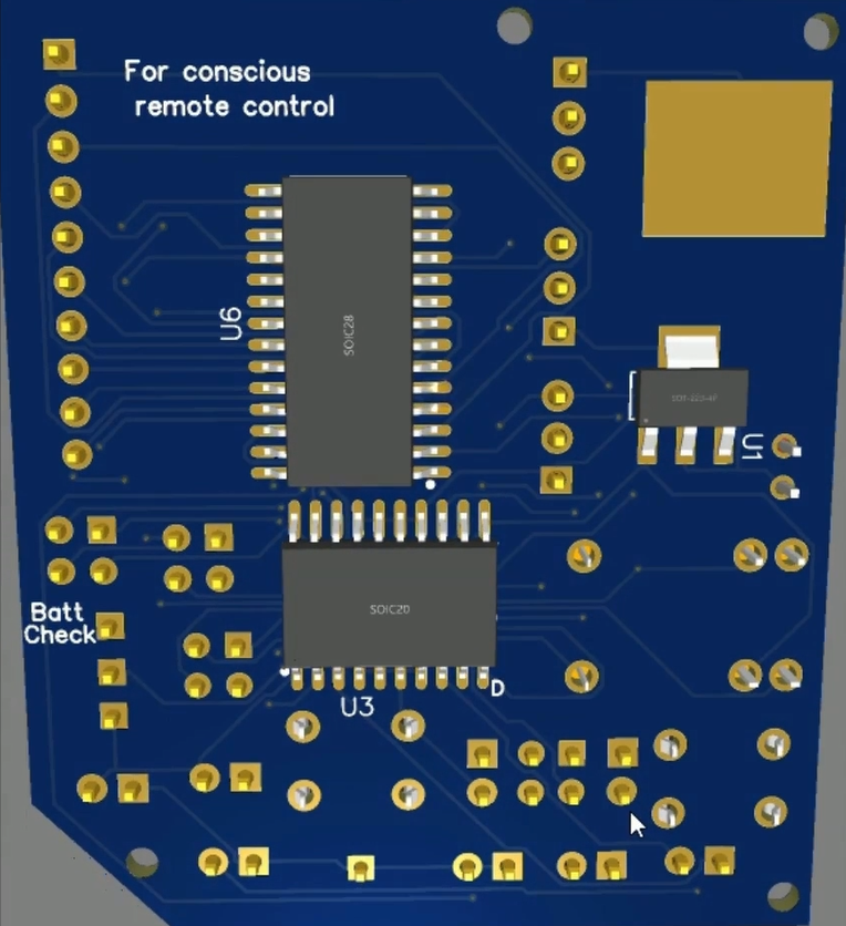
“For Conscious Remote Control”
is a phrase I added to the board to highlight the importance of human judgment in remote
operations. Even the most advanced AI cannot truly replace conscious human decisions, especially when unexpected
situations require flexible thinking and actions beyond predefined patterns, particularly when it is not possible
to be physically on site and there is an urgent need to close a valve or switch off a specific circuit.
For more information, check out the project on
GitHub
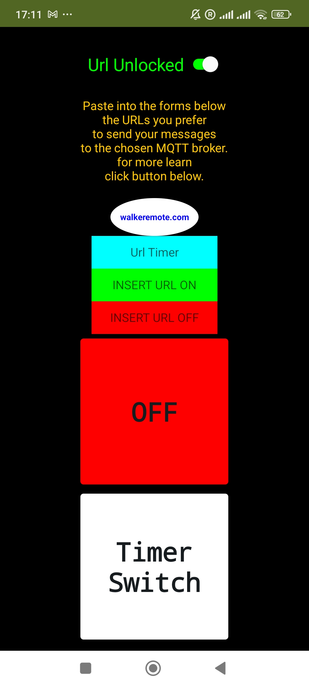
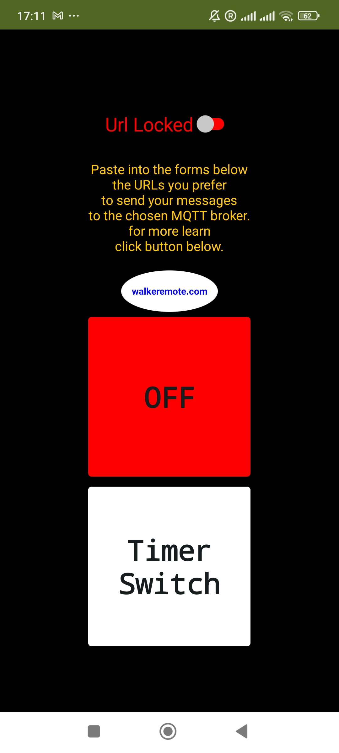
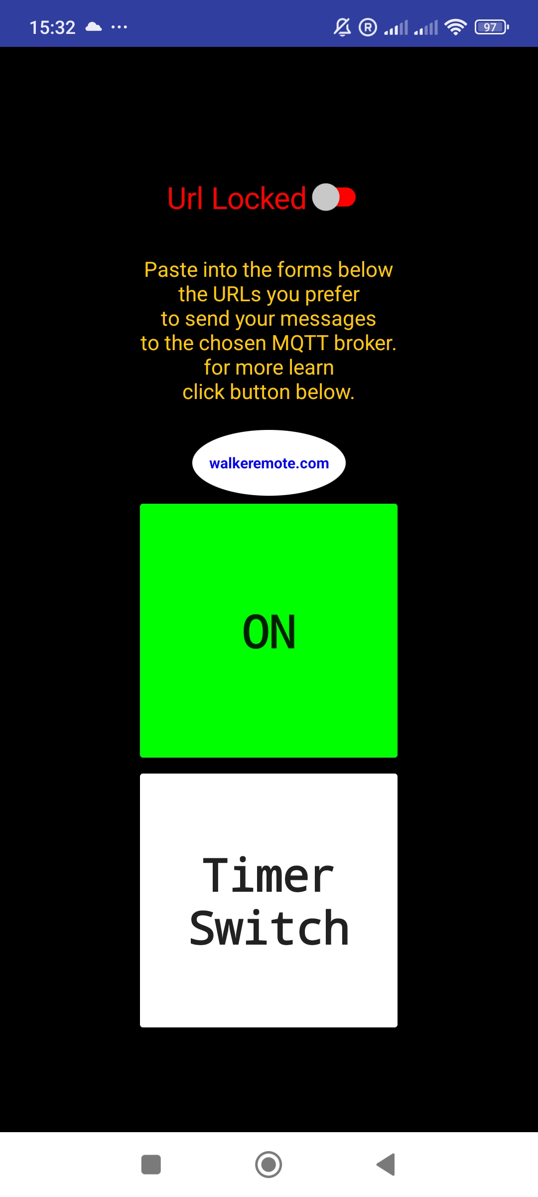
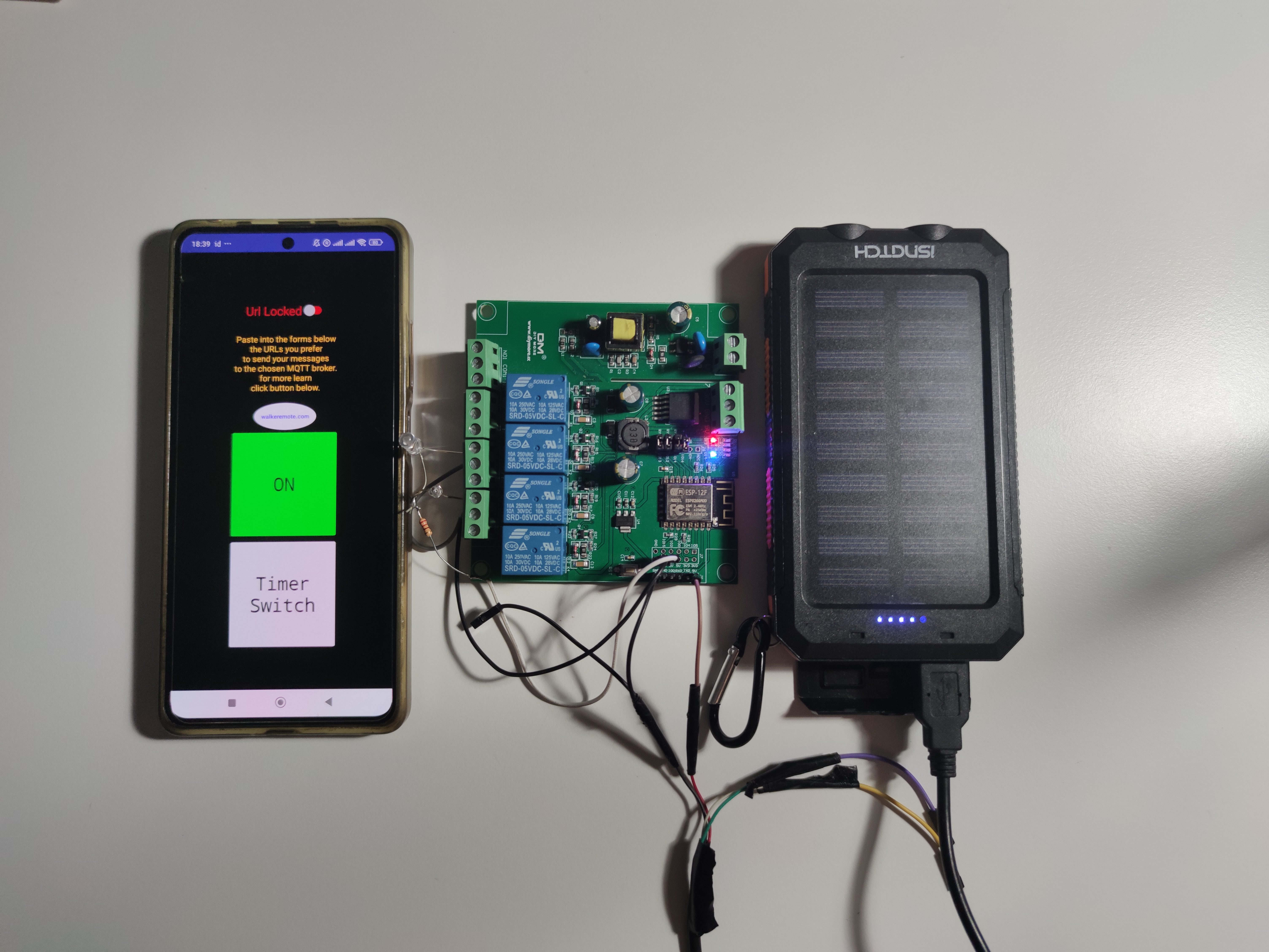
New WalkeremoteSwitch app for domotic use
I’ve been working on a new app, and I’d like to share a little preview here on the blog.
I’ve already posted a couple of photos that show how it works.
As you can see in the screenshots, the Lock/Unlock button lets you insert URLs that send MQTT commands to your hardware.
Once received, the hardware executes an action — for example, triggering a relay to switch on a lamp.
The app includes three forms:
The first one is for the timer URL. When you press the momentary button, the link points to a web page designed to send two MQTT messages:
one immediately when the button is pressed, and another after a delay that you can set directly in the URL.
This way, you can remotely trigger any kind of button.
The other two forms are dedicated to URLs for switching a relay ON and OFF, controlled by the green and red buttons.
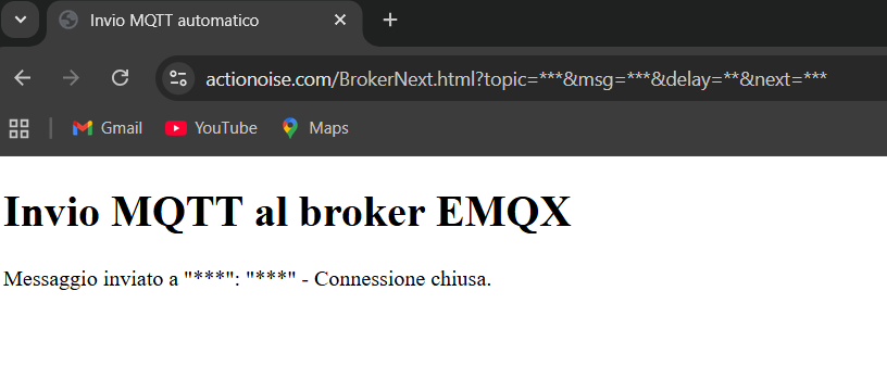
Using URLs to Control The WalkeremoteSwitch01 App
You can integrate two types of URLs into your app to send MQTT messages via a simple HTML page.
Once the links are clicked, the browser will open and indicate that the message has been sent.
You just need to replace the asterisks directly in the browser form as shown in the photo, as follows:
The same names used for the asterisks:
topic
msg
delay
next
will then be the same variables to use in the ESP8266 sketch, which will receive the preset messages and perform the chosen actions.
Below is the link to the video of the app in action.
I used the same home automation board that I used in the experiment described a few lines below
(you can find the topic here)
Today I started experimenting with the Meta Quest 3 sensors, using hand tracking as an interface to control home automation systems.
The idea is to transform natural gestures into intelligent commands, without the need for physical buttons or switches.
This connects directly to the concept of Web 4.0, where human–machine interaction becomes increasingly immersive, contextual, and personalized.
It’s no longer just about browsing content, but about merging the physical and digital worlds in real time, creating experiences where the web reacts to the body and the environment.
As a next step, I will also try to approach a motor control system, allowing me to control a walkeremoteboard through gestures.
The goal is to bring the same natural interaction logic into mobile robotics, combining virtual reality with physical automation.
Stay tuned on this page for upcoming news and developments.
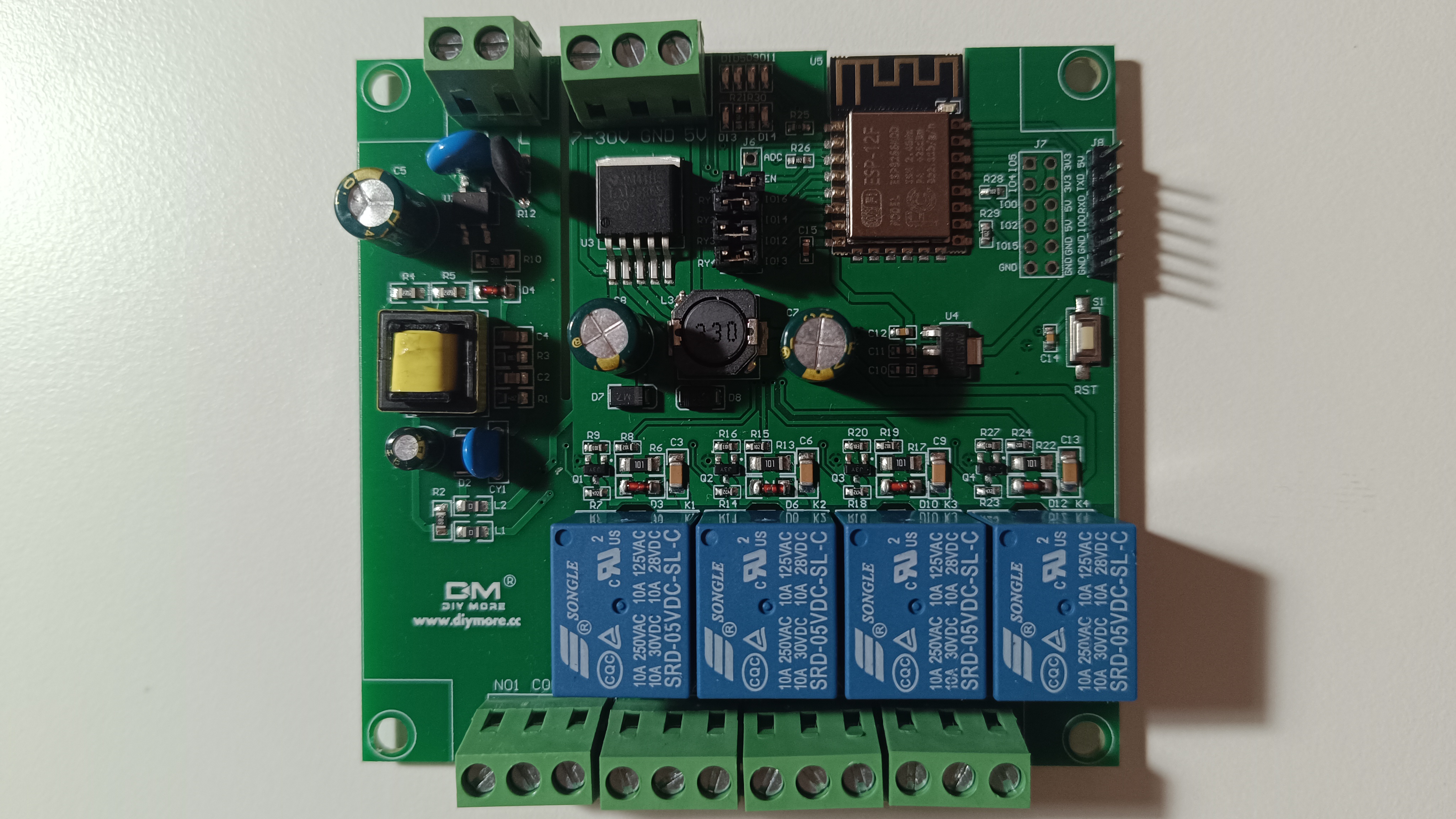
In this tutorial, we’ll take a look at a generic smart home relay board commonly found on platforms like AliExpress.
These boards are quite versatile, easy to program, and can be integrated with platforms like Walkeremote for remote control and automation.
Overview of the Board
The board featured in this tutorial was purchased from AliExpress:
in this Link
Include WiFi (ESP8266)
4 relays, each controllable individually
Multiple power input options:
220V AC, 7–30V DC, 5V DC
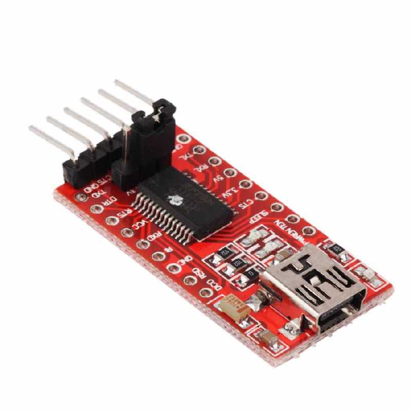
Programming pinouts, compatible with FTDI adapters
Extra GPIOs, which can be used to control motors, sensors, or other peripherals.
This makes it a great option for DIY home automation projects.
Programming the Board
The ESP8266 onboard makes it very easy to program this board using the Arduino IDE.
In this example (video link and code below), I’ve uploaded a generic sketch that connects the board to the Walkeremote platform,
allowing for MQTT-based remote control via topics and commands configured in the code.
Integration with Walkeremote platform
To control this board via the Walkeremote platform, simply flash the provided code with your specific MQTT credentials
(topics, command structure, etc.). Once set up, you can easily control each relay remotely from any device connected to Walkeremote.
#include <ESP8266WiFi.h>
#include <PubSubClient.h>

// WiFi credentials
const char* ssid = "yourSidWiFi";
const char* password = "yourPasswordWiFi";

// MQTT broker
const char* mqtt_server = "brokerMqttLink";
const int mqtt_port = 1883;
const char* mqtt_topic = "6653580bcf77af044070a45c";
const char* client_id = "mqttx_fa91203b";

// Mapping dei pin logici
const int pinD7 = 13;
const int pinD6 = 12;
const int pinD5 = 14;
const int pinD4 = 2;
const int pinD1 = 5;
const int pinD0 = 16;

WiFiClient espClient;
PubSubClient client(espClient);

void setup_pins() {
  digitalWrite(pinD1, HIGH);
  pinMode(pinD1 , OUTPUT);
  int pins[] = {pinD7, pinD6, pinD5, pinD0};
  for (int i = 0; i < 4; i++) {
    pinMode(pins[i], OUTPUT);
    digitalWrite(pins[i], LOW);
  }
}

void handleCommand(String msg) {
  msg.trim();

  if (msg.endsWith("665357ec0c4b136d3773e5ca")) {
    if (msg == "4350665357ec0c4b136d3773e5ca") digitalWrite(pinD7, HIGH);
    else if (msg == "5888665357ec0c4b136d3773e5ca") digitalWrite(pinD6, HIGH);
    else if (msg == "3395665357ec0c4b136d3773e5ca") digitalWrite(pinD5, HIGH);
    else if (msg == "3305665357ec0c4b136d3773e5ca") digitalWrite(pinD0, HIGH);
    else if (msg == "3311665357ec0c4b136d3773e5ca") digitalWrite(pinD7, LOW);
    else if (msg == "8380665357ec0c4b136d3773e5ca") digitalWrite(pinD6, LOW);
    else if (msg == "9983665357ec0c4b136d3773e5ca") digitalWrite(pinD5, LOW);
    else if (msg == "9903665357ec0c4b136d3773e5ca") digitalWrite(pinD0, LOW);
  }
  Serial.print("Eseguito comando: ");
  Serial.println(msg);
}

void callback(char* topic, byte* payload, unsigned int length) {
  String msg;
  for (unsigned int i = 0; i < length; i++) {
    msg += (char)payload[i];
  }

  Serial.print("Messaggio ricevuto [");
  Serial.print(topic);
  Serial.print("]: ");
  Serial.println(msg);

  handleCommand(msg);
}

void setup_wifi() {
  delay(10);
  Serial.println();
  Serial.print("Connettendo al WiFi: ");
  Serial.println(ssid);

  WiFi.begin(ssid, password);
  int tentativi = 0;

  while (WiFi.status() != WL_CONNECTED) {
    delay(500);
    Serial.print(".");
    tentativi++;
    if (tentativi > 30) {
      Serial.println("Errore WiFi. Riavvio...");
      ESP.restart();
    }
  }

  Serial.println("\nWiFi connesso. IP: " + WiFi.localIP().toString());
}

void reconnect() {
  while (!client.connected()) {
    Serial.print("Connessione al broker MQTT... ");
    if (client.connect(client_id)) {
      Serial.println("Connesso!");
      client.subscribe(mqtt_topic);
      Serial.println("Sottoscritto a: " + String(mqtt_topic));
      digitalWrite(pinD1, LOW);
    } else {
      Serial.print("Fallito, rc=");
      Serial.print(client.state());
      Serial.println(". Ritento in 5 secondi.");
      digitalWrite(pinD1, HIGH);
      delay(5000);
    }
  }
}

void setup() {
  Serial.begin(115200);
  setup_pins();
  setup_wifi();
  client.setServer(mqtt_server, mqtt_port);
  client.setCallback(callback);
}

void loop() {
  if (!client.connected()) {
    reconnect();
  }
  client.loop();
}
Published by Michele Tavolacci on
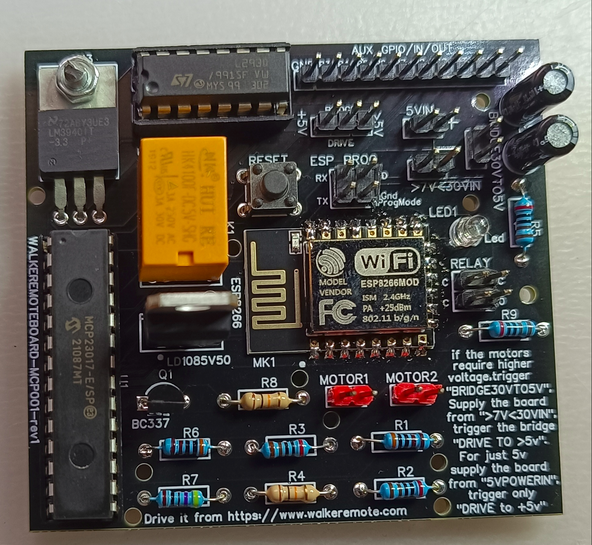
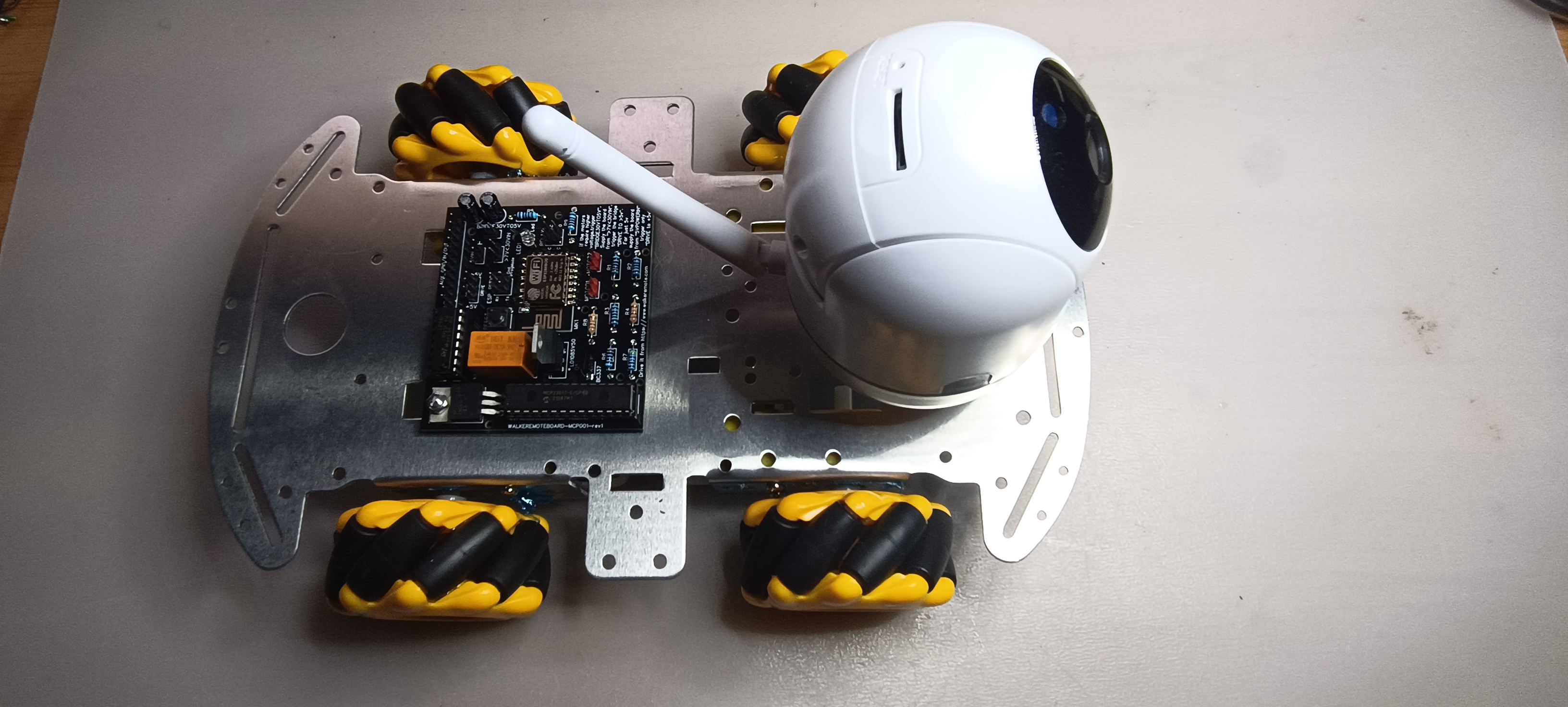
New Walkeremoteboard-mcp001-rev1
Easy to use yet offering advanced control capabilities, the Walkeremoteboard-mcp001-rev1 is designed to effortlessly manage Relay,
Stepper, Brushless, and wheel motors, accommodating voltages from 5V to 27V with appropriate bridges.
The onboard L293D driver facilitates direct usage of wheel motors, while an integrated relay allows for convenient control of headlights.
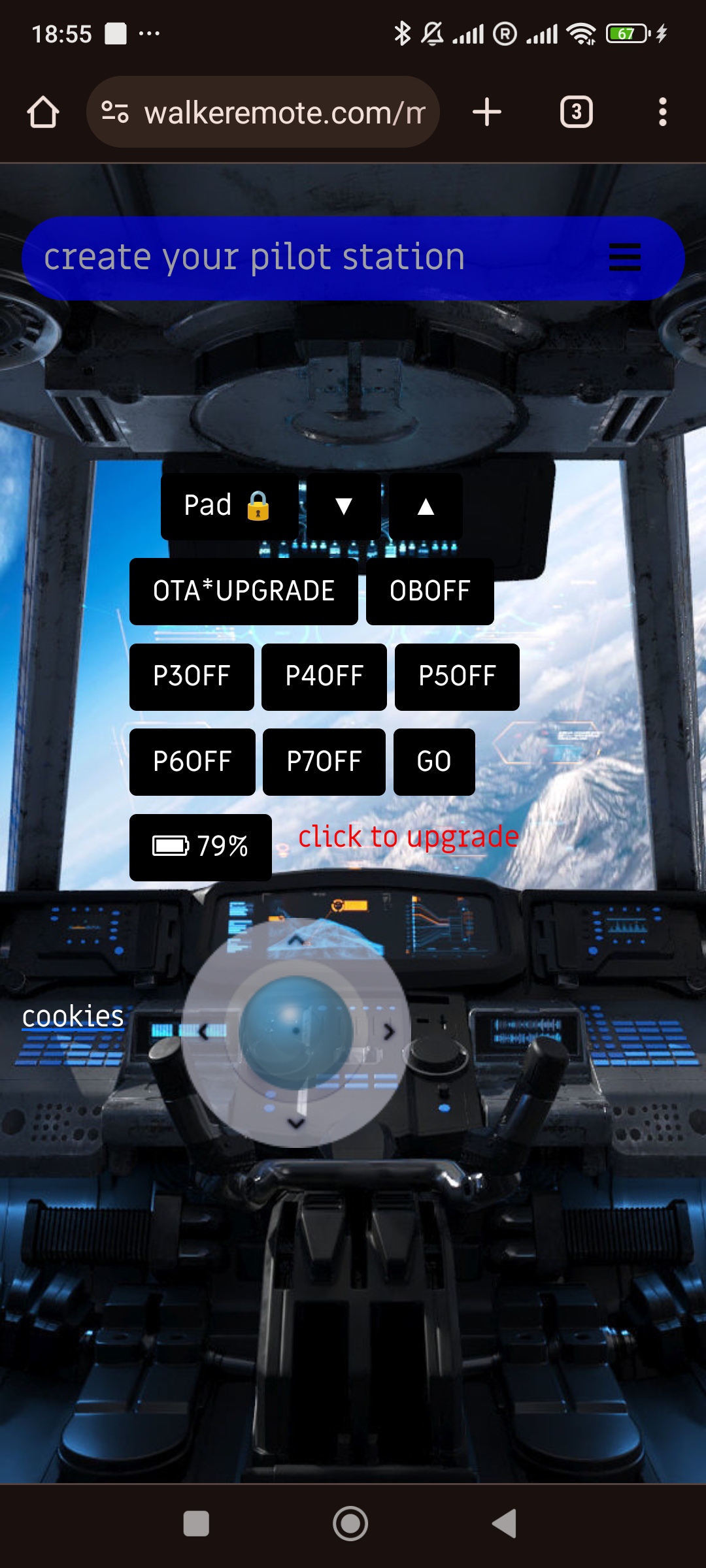
With 10 auxiliary pinouts, users can activate additional functionalities via auxiliary controls, already available in their own pilot station accessible on our website.
Additionally, accessing your pilot station is as simple as scanning the QR code on the board to obtain the email and password for login.
Moreover, with the new firmware, the board ensures it never loses internet connection.
In the event of disconnection while in operation, the motors will rotate in reverse for 20 seconds, allowing the board to reconnect within the WiFi coverage area.
The Walkeremoteboard has been enhanced with the latest firmware, which can be conveniently installed directly from the dedicated command page.
By clicking the OTA UPGRADE button, the button will flash for a few seconds, and the Walkeremoteboard will have the multicolor LED turned off and the blue LED of the microcontroller turned on.
Once the OTA update operation is completed, the button on the command page will stop flashing, displaying a green color with the "successfull" message.
The blue LED on the board will turn off, while the multicolor LED indicating the connection to the server will be lit.
For first wifi setting connection
CLICK HERE for Youtube tutorial
Published by Michele Tavolacci on
Last Upgrade
Added the ability to monitor the battery status powering the walkeremoteboard through the percentage displayed on the command page.
An email will be sent from the board notifying the user that the battery has reached a minimum threshold and needs to go back to the docking station to recharge.
WALKEREMOTEBOARD SIMPLE TO USE FOR IOT EXPERIMENTAL PROJECTS
dev/board esp8266 onboard programmed for use it from walkeremote portal
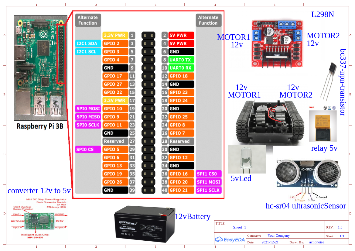
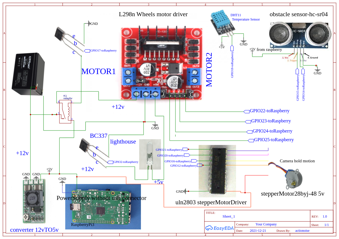
CREATE YOURSELF A TELEPRESENCE SYSTEM HOMEMADE WITH A RASPBERRY AND ARDUINO
Welcome to walkeremote portal. Sign Up to create your pilot station for telepresence system
with use of Raspberry,
actionoiseboards,
old notebook or mobile phone for recycle it.
For Actionoiseboard Hardware and general Tutorials:
HERE
Below last script updated and schematics.
Use of pilot station with notebook keyboard:
arrow keys for direction, k=nord, l=sud
p=Gohead, x=stop.
Reboot from pilot station:
write the number 888 in first arrow form and click red button send, immediately need to change the parameter for avoid the continuous reboot of Dev Board.
SwitchOn lighthouse in GPIO2:
write lon in first arrow form and click send red button.
SwitchOff lighthouse in GPIO2:
write lof in first arrow form and click send red button.
switch on Relay1 from ActionoiseRemoteModule:
write h1 in first arrow form and click send red button.
switch on Relay2 from ActionoiseRemoteModule:
write h2 in first arrow form and click send red button.
switch on Relay3 from ActionoiseRemoteModule:
write h3 in first arrow form and click send red button.
switch on Relay4 from ActionoiseRemoteModule:
write h4 in first arrow form and click send red button.
After registration an email with credentials will be received, copy and paste the credentials to blank form in ADD DB menu button and inside the db variable of python script below.
Example of python code to read database's values
#copy and paste this code in a file py with name Neww.py

import stop
import pymysql.cursors
import RPi.GPIO as GPIO
import time
import subprocess
from threading import Timer
from RpiMotorLib import RpiMotorLib
from smbus import SMBus
addr = 0x8
bus = SMBus(1)

GPIO.setmode(GPIO.BCM)
nord=[21,20,16,12]
sud=[12,16,20,21]
obstacle=0
mymotor=RpiMotorLib.BYJMotor('MyMotorOne','28BYJ')
GPIO.setup(21,GPIO.OUT)
GPIO.setup(20,GPIO.OUT)
GPIO.setup(16,GPIO.OUT)
GPIO.setup(12,GPIO.OUT)
GPIO.setup(2,GPIO.OUT)
GPIO.setup(17,GPIO.OUT)
GPIO.setup(22,GPIO.OUT)
GPIO.setup(23,GPIO.OUT)
GPIO.setup(24,GPIO.OUT)
GPIO.setup(5,GPIO.OUT)
GPIO.output(17,GPIO.HIGH)

db=pymysql.connect(host="",port=3306,user="",password="",db="",charset="utf8mb4")
cursor=db.cursor()
sql="SELECT comandi FROM pilotino"
cur=cursor.execute(sql)
result=cursor.fetchone()

GoHeadTime="SELECT gohead from MotionTime"
time1=cursor.execute(GoHeadTime)
result1=cursor.fetchone()

GoBottomTime="SELECT gobottom from MotionTime"
time2=cursor.execute(GoBottomTime)
result2=cursor.fetchone()

GoRight="SELECT goright from MotionTime"
time3=cursor.execute(GoRight)
result3=cursor.fetchone()

GoLeft="SELECT goleft from MotionTime"
time4=cursor.execute(GoLeft)
result4=cursor.fetchone()

Gorallent="SELECT goralle from MotionTime"
time5=cursor.execute(Gorallent)
result5=cursor.fetchone()

for a in result1:
    print(a+" gohead-time-variable")

for e in result5:
    print(e+" gorallent-time-variable")

for b in result2:
    print(b+" bottom-time-variable")

for d in result3:
    print(d+" bottom-time-variable")

for c in result4:
    print(c+" right-time-variable")

def check():
    if(cur > 0):
        for x in result:
            if(x=="h"):
                print("right")
                GPIO.output(22,GPIO.LOW)
                GPIO.output(23,GPIO.HIGH)
                GPIO.output(24,GPIO.HIGH)
                GPIO.output(5,GPIO.LOW)
                time.sleep(float(d))
                GPIO.output(22,GPIO.LOW)
                GPIO.output(23,GPIO.LOW)
                GPIO.output(24,GPIO.LOW)
                GPIO.output(5,GPIO.LOW)
                via()

            if(x=='nord'):
                print('nord')
                mymotor.motor_run(sud, .1/50,30,False,False,'half', .100)
                via()

            if(x=='sud'):
                print('sud')
                mymotor.motor_run(nord, .1/50,30,False,False,'half', .100)
                via()

            if(x=="g"):
                print("left")
                GPIO.output(22,GPIO.HIGH)
                GPIO.output(23,GPIO.LOW)
                GPIO.output(24,GPIO.LOW)
                GPIO.output(5,GPIO.HIGH)
                time.sleep(float(c))
                GPIO.output(22,GPIO.LOW)
                GPIO.output(23,GPIO.LOW)
                GPIO.output(24,GPIO.LOW)
                GPIO.output(5,GPIO.LOW)
                via()

            if(x=="b"):
                print("bottom")
                GPIO.output(22,GPIO.HIGH)
                GPIO.output(23,GPIO.LOW)
                GPIO.output(24,GPIO.HIGH)
                GPIO.output(5,GPIO.LOW)
                time.sleep(float(b))
                GPIO.output(22,GPIO.LOW)
                GPIO.output(23,GPIO.LOW)
                GPIO.output(24,GPIO.LOW)
                GPIO.output(5,GPIO.LOW)
                via()

            if(x=="ra"):
                print("GoRallent")
                GPIO.output(22,GPIO.LOW)
                GPIO.output(23,GPIO.HIGH)
                GPIO.output(24,GPIO.LOW)
                GPIO.output(5,GPIO.HIGH)
                time.sleep(float(e))
                GPIO.output(22,GPIO.LOW)
                GPIO.output(23,GPIO.LOW)
                GPIO.output(24,GPIO.LOW)
                GPIO.output(5,GPIO.LOW)
                via()

            if(x=="y"):
                print("go no obstacle")
                GPIO.output(22,GPIO.LOW)
                GPIO.output(23,GPIO.HIGH)
                GPIO.output(24,GPIO.LOW)
                GPIO.output(5,GPIO.HIGH)
                time.sleep(float(a))
                GPIO.output(22,GPIO.LOW)
                GPIO.output(23,GPIO.LOW)
                GPIO.output(24,GPIO.LOW)
                GPIO.output(5,GPIO.LOW)
                via()

    if(cur==0):
        print("no command inserted")
        db.close()
        quit()

    via()

def via():
    canc="delete from pilotino"
    cursor.execute(canc)
    db.commit()
    db.close()
    quit()

if(a=='888'):
    subprocess.Popen(['sudo','reboot','-h','now'])

if(a == 'lon'):
    GPIO.output(2,GPIO.HIGH)

if (a=='lof'):
    GPIO.output(2,GPIO.LOW)

if (a == "h1"):
    bus.write_byte(addr, 0x1)
    dele="delete from MotionTime"
    cursor.execute(dele)
    db.commit()
    delay(2)
    quit()

if (a == "h2"):
    bus.write_byte(addr, 0x2)
    dele="delete from MotionTime"
    cursor.execute(dele)
    db.commit()
    delay(2)
    quit()

if (a == "h3"):
    bus.write_byte(addr, 0x3)
    dele="delete from MotionTime"
    cursor.execute(dele)
    db.commit()
    delay(2)
    quit()

if (a == "h4"):
    bus.write_byte(addr, 0x4)
    dele="delete from MotionTime"
    cursor.execute(dele)
    db.commit()
    delay(2)
    quit()

check()
db.close()
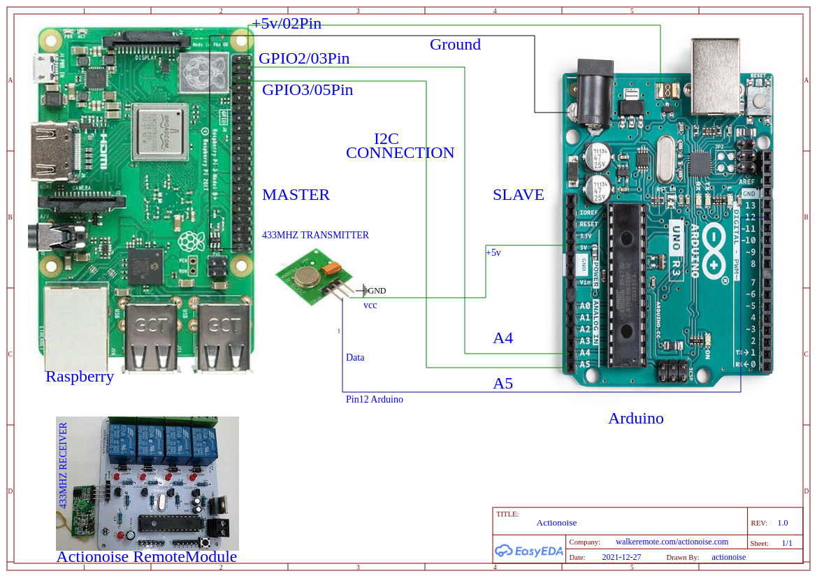
ArduinoCode for i2c connection.
//arduino code for use of ActionoiseRemote Module/433mhz
//arduino connected to raspberry with i2c module

#include <Wire.h>
#include <VirtualWire.h>
int a = 0;
int b= 0;
int t= 0;
int d=0;
int f=0;

void setup() {
  Wire.begin(0x8);
  Wire.onReceive(receiveEvent);
}

void receiveEvent(int howMany) {
  while (Wire.available()) {
    char c = Wire.read();
    if(c == 0x1){
      a = 1;
    }
    if(c == 0x2){
      b = 1;
    }
    if(c == 0x3){
      t = 1;
    }
    if(c == 0x4){
      d = 1;
    }
    if(c==0x6){
      f=1;
    }
  }
}

void loop() {
  if (a == 1){
    vw_set_ptt_inverted(true);
    vw_setup(4000);
    const char *msg = "A";
    vw_send((uint8_t *)msg, strlen(msg));
    vw_wait_tx();
    delay(500);
    a=0;
  }

  if (b == 1){
    vw_set_ptt_inverted(true);
    vw_setup(4000);
    const char *msg = "B";
    vw_send((uint8_t *)msg, strlen(msg));
    vw_wait_tx();
    delay(500);
    b=0;
  }

  if (t == 1){
    vw_set_ptt_inverted(true);
    vw_setup(4000);
    const char *msg = "C";
    vw_send((uint8_t *)msg, strlen(msg));
    vw_wait_tx();
    delay(500);
    t=0;
  }

  if (d == 1){
    vw_set_ptt_inverted(true);
    vw_setup(4000);
    const char *msg = "D";
    vw_send((uint8_t *)msg, strlen(msg));
    vw_wait_tx();
    delay(500);
    d=0;
  }
}
PythonCode for HC-sr04 ultrasonic sensor
#obstacle sensor detect
#copy and paste this code in a file py with name stop.py
import subprocess
import pymysql.cursors
import Neww
import RPi.GPIO as GPIO
from Bluetin_Echo import Echo
GPIO.setwarnings(False)
TRIGGER_PIN = 15
ECHO_PIN = 14
speed_of_sound = 250
echo = Echo(TRIGGER_PIN, ECHO_PIN, speed_of_sound)
samples = 10
resu = echo.read('cm', samples)
obstacle=0
GPIO.setmode(GPIO.BCM)
GPIO.setwarnings(False)
db=pymysql.connect(host="",port=3306,user="",password="",db="",charset="utf8mb4")
cursor=db.cursor()
sql="SELECT comandi FROM pilotino"
cur=cursor.execute(sql)
result=cursor.fetchone()

GPIO.setup(22,GPIO.OUT)
GPIO.setup(23,GPIO.OUT)
GPIO.setup(24,GPIO.OUT)
GPIO.setup(5,GPIO.OUT)

if (resu < 40):
    print('obstacle detected')
    GPIO.output(22,GPIO.LOW)
    GPIO.output(23,GPIO.LOW)
    GPIO.output(24,GPIO.LOW)
    GPIO.output(5,GPIO.LOW)
    canc="delete from pilotino"
    cursor.execute(canc)
    db.commit()
    subprocess.call(['sh','./close.sh'])

print ('no obstacle detected')
PythonCode for DHT11 Temperature Sensor.
#Humidity/Temeperature sensor DHT11 +
#Raspberry CPU Reader +
#DataTime
#copy and paste in a file with temp.py name
#Code in Action from remote place in link below:
#https://www.actionoise.com/tempr.php
from gpiozero import CPUTemperature
from datetime import datetime
from threading import Timer
import pymysql.cursors
import Adafruit_DHT
cpu=CPUTemperature()
internal=(cpu.temperature)
sensor=Adafruit_DHT.DHT11
pin=18
humidity,temperature = Adafruit_DHT.read_retry(sensor,pin)

db=pymysql.connect(host="",port=3306,user="",password="",db="",charset="utf8mb4")
cursor=db.cursor()
data1=datetime.now()

def tira():
    canc="delete from sensor"
    cursor.execute(canc)
    db.commit()
    quit()

def rimbalzo():
    humidity,temperature = Adafruit_DHT.read_retry(sensor,pin)
    data1=datetime.now()
    sql= "insert into sensor (temp,hum,date,cpu) values (%s,%s,%s,%s)"
    cursor.execute(sql,(temperature,humidity,data1,internal))
    db.commit()
    Timer(10.0, tira).start()

rimbalzo()
copy and paste this code below and rename close.sh
#!/bin/bash
killall python3
below 3 last sh file for launch the py script in autostart copy paste and rename in 3 sh file Below the sh for launch the Neww.py script. Rename it in launch.sh
#!/bin/bash
while true;
do
python3 Neww.py;done
below the sh file for launch the stop.py script.rename it in stoppa.sh
#!/bin/bash
while true;
do
python3 stop.py;done
below the sh file for launch the temp.py script.rename it in temp.sh
#!/bin/bash
while true;
do
python3 temp.py;done
Now there are 2 file python Neew.py - stop.py
and 3 sh file that whe can rename: close.sh - launch.sh - stoppa.sh
insert all file inside the folder pi of your raspberry and digit in terminal for every file: sudo chmod 777 filename for admin permission.
At the end go to autostart file, from terminal digit:
cd ../../etc/xdg/lxsession/LXDE-pi
inside LXDE-pi digit: sudo nano autostart
add to file this two string:
@lxterminal -e /home/pi/launch.sh
@lxterminal -e /home/pi/stoppa.sh
press ctrl + x and y at the end and finish, reboot the raspberry and you can see in your screen the 2 file py launch it in autostart.
Follow the Actionoise Twitch channel and join to live for more tutorials and try yourself from remote the raspberry robocars.
Database's tables and rows creation
Create inside the db a table with name MotionTime and inside this one create 5 columns with same order and name like below:
gobottom gohead goleft goralle goright,
select VARCHAR in variable form and 128 in length form, same for every column.
create another table inside the same db with name pilotino and inside pilotino create a column with name:
comandi and same VARCHAR variable and 128 in length form.
for resolve error about max_connections, just need modify the mysql global variable max_connections.
digit in mysql console: SHOW VARIABLES LIKE "MAX_CONNECTIONS";
and in case of a value low increase with the command:
SET GLOBAL MAX CONNECTIONS=10000; Press CTRL+Enter from phpmyadmin
SET GLOBAL WAIT_TIMEOUT=1; Press CTRL+Enter from phpmyadmin
For temperature and humidity sensor inside the same database, create a table with name sensor, and inside create 4 columns with the same name and order:
temp hum date cpu
with VARCHAR variable and 128 of length.
Send Commands with MQTT protocol.
Another solution to send commands from remote is the MQTT protocol,
the same to use for Internet of things.
Below the python script for the raspberry car and for the remote device used for send message-commands.
#install before the paho.mqtt library
#and start this script inside a raspberry
#assembled with same schematic up this page
from RpiMotorLib import RpiMotorLib
import paho.mqtt.client as mqtt
import RPi.GPIO as GPIO
GPIO.setmode(GPIO.BCM)
import time
GPIO.setmode(GPIO.BCM)

nord=[21,20,16,12]
sud=[12,16,20,21]
mymotor=RpiMotorLib.BYJMotor('MyMotorOne','28BYJ')
GPIO.setup(21,GPIO.OUT)
GPIO.setup(20,GPIO.OUT)
GPIO.setup(16,GPIO.OUT)
GPIO.setup(12,GPIO.OUT)
GPIO.setup(17,GPIO.OUT)
GPIO.setup(22,GPIO.OUT)
GPIO.setup(23,GPIO.OUT)
GPIO.setup(24,GPIO.OUT)
GPIO.setup(5,GPIO.OUT)
GPIO.output(17,GPIO.HIGH)

def on_connect(client, userdata, flags, rc):
    print(f"connected with result code {rc}")
    client.subscribe(".....")

mymessage =''

def on_message(client,userdata,msg):
    global mymessage
    mymessage = str (f"{msg.payload}")
    print (mymessage)
    if(mymessage== "b'nord'"):
        print('comando ricevuto')
        mymotor.motor_run(sud, .1/50,30,False,False,'half', .100)

    if(mymessage=="b'sud'"):
        print('comando ricevuto')
        mymotor.motor_run(nord, .1/50,30,False,False,'half', .100)

    if(mymessage=="b'right'"):
        print("right")
        GPIO.output(22,GPIO.LOW)
        GPIO.output(23,GPIO.HIGH)
        GPIO.output(24,GPIO.HIGH)
        GPIO.output(5,GPIO.LOW)
        time.sleep(float(0.4))
        GPIO.output(22,GPIO.LOW)
        GPIO.output(23,GPIO.LOW)
        GPIO.output(24,GPIO.LOW)
        GPIO.output(5,GPIO.LOW)

    if(mymessage=="b'stop'"):
        print("stop")
        GPIO.output(22,GPIO.LOW)
        GPIO.output(23,GPIO.LOW)
        GPIO.output(24,GPIO.LOW)
        GPIO.output(5,GPIO.LOW)

    if(mymessage=="b'left'"):
        print("left")
        GPIO.output(22,GPIO.HIGH)
        GPIO.output(23,GPIO.LOW)
        GPIO.output(24,GPIO.LOW)
        GPIO.output(5,GPIO.HIGH)
        time.sleep(float(0.4))
        GPIO.output(22,GPIO.LOW)
        GPIO.output(23,GPIO.LOW)
        GPIO.output(24,GPIO.LOW)
        GPIO.output(5,GPIO.LOW)

    if(mymessage=="b'bottom'"):
        print("bottom")
        GPIO.output(22,GPIO.HIGH)
        GPIO.output(23,GPIO.LOW)
        GPIO.output(24,GPIO.HIGH)
        GPIO.output(5,GPIO.LOW)
        time.sleep(float(0.4))
        GPIO.output(22,GPIO.LOW)
        GPIO.output(23,GPIO.LOW)
        GPIO.output(24,GPIO.LOW)
        GPIO.output(5,GPIO.LOW)

    if(mymessage=="b'gora'"):
        print("GoRallent")
        GPIO.output(22,GPIO.LOW)
        GPIO.output(23,GPIO.HIGH)
        GPIO.output(24,GPIO.LOW)
        GPIO.output(5,GPIO.HIGH)
        time.sleep(float(0.4))
        GPIO.output(22,GPIO.LOW)
        GPIO.output(23,GPIO.LOW)
        GPIO.output(24,GPIO.LOW)
        GPIO.output(5,GPIO.LOW)

    if(mymessage=="b'go'"):
        print("go no obstacle")
        GPIO.output(22,GPIO.LOW)
        GPIO.output(23,GPIO.HIGH)
        GPIO.output(24,GPIO.LOW)
        GPIO.output(5,GPIO.HIGH)

client = mqtt.Client()
client.on_connect = on_connect
client.on_message = on_message
client.will_set("raspberry/status",b'{"status":"off"}')
client.connect("broker.emqx.io",1883,60)

client.loop_forever()
Below Python script for send message-commands with mqtt protocol from remote device.
#install in your remote device the mqtt library:
#pip3 install paho-mqtt
#create a profile in remote server broker:
#https://mqttx.app/ or dowload the app
#List of remote server broker free in link below:
#https://github.com/mqtt/mqtt.org/wiki/brokers
#commads: arrow key for direction,
#backspace for stop,
#n key for move the camera up,
#s key for move the camera frame down.
#sudo pip3 install keyboard
#create a file with name mqtt.py

import paho.mqtt.client as mqtt
import time
import keyboard

def stoppa():
    mqttc = mqtt.Client()
    mqttc.connect("broker.emqx.io", 1883, 60)
    mqttc.loop_start()
    mqttc.publish(".....", "stop")
    mqttc.loop_stop()

while(1<2):
    while keyboard.is_pressed("s"):
        mqttc = mqtt.Client()
        mqttc.connect("broker.emqx.io", 1883, 60)
        mqttc.loop_start()
        mqttc.publish("........", "sud")
        mqttc.loop_stop()

    while keyboard.is_pressed("n"):
        mqttc = mqtt.Client()
        mqttc.connect("broker.emqx.io", 1883, 60)
        mqttc.loop_start()
        mqttc.publish(".......", "nord")
        mqttc.loop_stop()

    while keyboard.is_pressed("up arrow"):
        mqttc = mqtt.Client()
        mqttc.connect("broker.emqx.io", 1883, 60)
        mqttc.loop_start()
        mqttc.publish("........", "go")
        mqttc.loop_stop()

    while keyboard.is_pressed("down arrow"):
        mqttc = mqtt.Client()
        mqttc.connect("broker.emqx.io", 1883, 60)
        mqttc.loop_start()
        mqttc.publish(".......", "bottom")
        mqttc.loop_stop()

    while keyboard.is_pressed("left arrow"):
        mqttc = mqtt.Client()
        mqttc.connect("broker.emqx.io", 1883, 60)
        mqttc.loop_start()
        mqttc.publish("......", "right")
        mqttc.loop_stop()

    while keyboard.is_pressed("right arrow"):
        mqttc = mqtt.Client()
        mqttc.connect("broker.emqx.io", 1883, 60)
        mqttc.loop_start()
        mqttc.publish(".....", "left")
        mqttc.loop_stop()

    while keyboard.is_pressed("g"):
        mqttc = mqtt.Client()
        mqttc.connect("broker.emqx.io", 1883, 60)
        mqttc.loop_start()
        mqttc.publish("........", "go")
        mqttc.loop_stop()

    while keyboard.is_pressed("space"):
        mqttc = mqtt.Client()
        mqttc.connect("broker.emqx.io", 1883, 60)
        mqttc.loop_start()
        mqttc.publish(".......", "stop")
        mqttc.loop_stop()
Published by Michele Tavolacci on
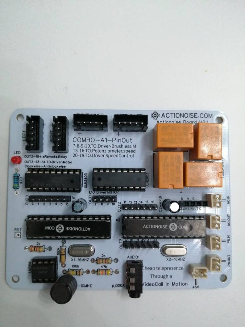
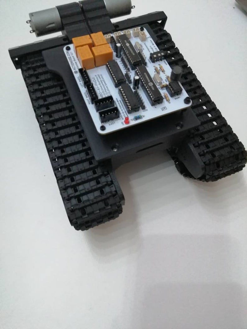
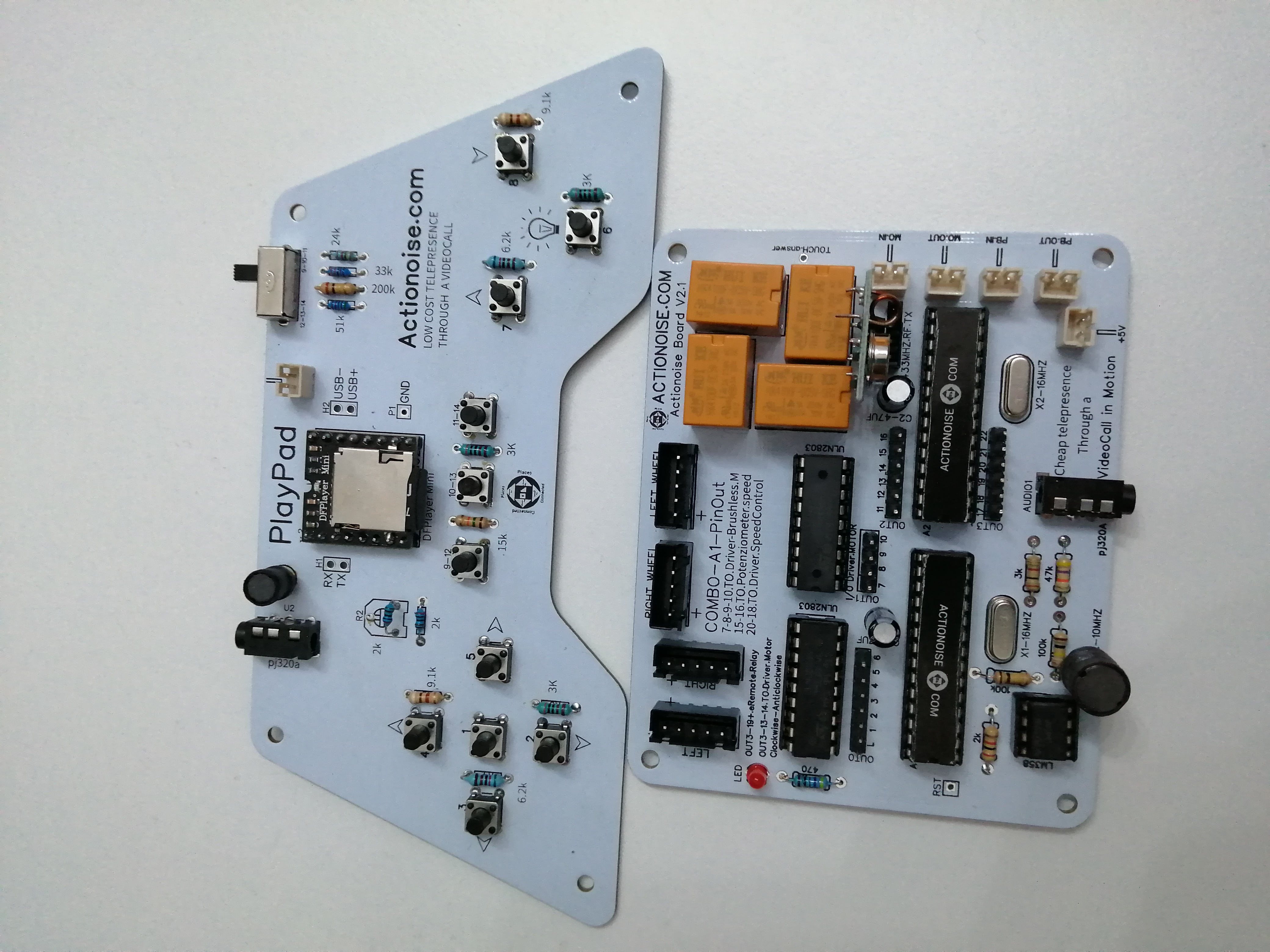
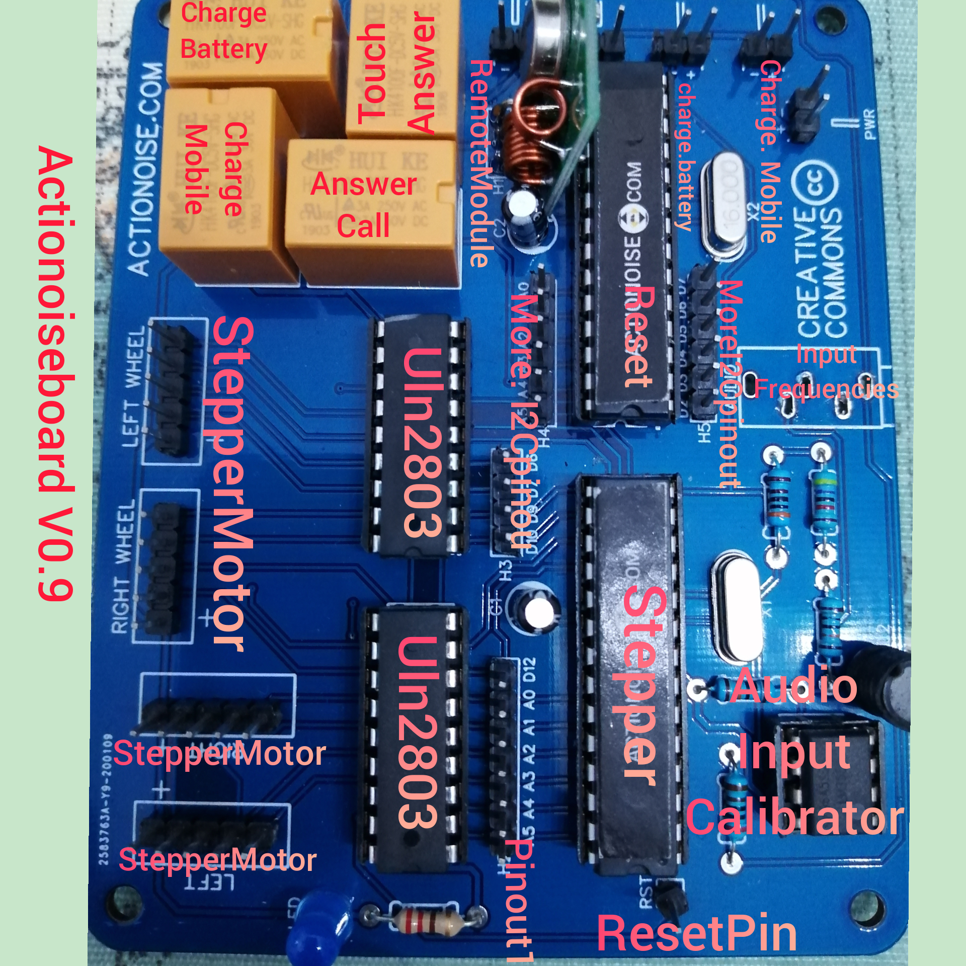
Actionoiseboard Recycling Old Phones into Functional Control Systems
Actionoise was born from a simple idea: reusing old cell phones destined for the trash by turning them into remote control tools.
By exploiting their audio channel, it was possible to transmit sound impulses capable of switching relays or moving motors remotely,
even through a simple video call.
This approach avoided reliance on cloud platforms, keeping the system essential, direct, and rooted in technological reuse.
That experiment represented an alternative way of thinking about automation:
not necessarily expensive or tied to external services, but creative, accessible, and sustainable.
Today Actionoise does not disappear but instead merges into Walkeremote, carrying with it all the experience it has accumulated.
On this site you will find the key content from the old project, alongside new ideas and developments related to automation, telepresence, and remote systems. 📦 ActionoiseFile Collection
Remaining on the topic of audio waves, I also came up with the idea of creating a joypad called Playpad.
This device works as an MP3 player for audio tracks. Once connected to the calling phone via jack, it allows the user to send the correct audio track through dedicated buttons,
in order to remotely control the Actionoiseboard.
The entire project was showcased at the Maker Faire (in 2019), where I presented archive videos and images of the system by clicking image:
The logo below belongs to the company that supported me in the development of all the electronic boards.
By clicking on it, you can download the various Gerber files of the boards.